| Pump
Basics
How A Centrifugal Pump Works A centrifugal pump is of very simple design. The only moving part is an impeller attached to a shaft that is driven by the motor.
Water enters the eye of the impeller and is thrown out by centrifugal force. As water leaves the eye of the impeller a low pressure area is created causing more liquid to flow toward the inlet because of atmospheric pressure and centrifugal force. Velocity is developed as the liquid flows through the impeller while it is running at high speeds on the shaft. The liquid velocity is collected by the diffuser or volute and converted to pressure by special designed passageways that direct the flow to discharge into the piping system; or, on to another impeller stage for further increasing to pressure. The head or pressure that a pump will develop is in direct relation to the impeller diameter, the number of impellers, the eye or inlet opening size, and how much velocity is developed from the speed of the shaft rotation. Capacity is determined by the exit width of the impeller. All of these factors affect the horsepower size of the motor to be used; the more water to be pumped or pressure to be developed, the more energy is needed. A centrifugal pump is not positive acting. As the depth to water increases, it pumps less and less water. Also, when it pumps against increasing pressure it pumps less water. For these reasons it is important to select a centrifugal pump that is designed to do a particular pumping job. For higher pressures or greater lifts, two or more impellers are commonly used; or, a jet injector is added to assist the impeller in raising the pressure. What
Pump Do I Need?
JET PUMPS
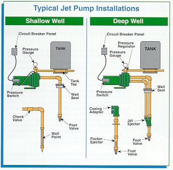
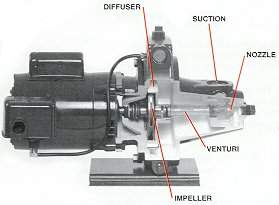
For a jet nozzle to be effective it must be combined with a venturi. The venturi changes the high-speed jet strained back into a high-pressure for delivery to the centrifugal pump. The jet and venturi are simple in appearance but they have to be well engineered and carefully matched to be efficient for various pumping conditions. The jet nozzle and venturi are also known as ejectors/ejector kits. On a shallow-well jet pump the injector kit (jet nozzle and venturi) is located in the pump housing in front of impeller.
The difference between a deep-well jet pump and a shallow-well jet pump is the location of the injector. The deep-well injector is located in the well below the water level. The deep-well injector works in the same way as the shallow-well ejector. Water is supplied to it under pressure from the pump. The ejector then returns the water plus an additional supply from the well, to a level where the centrifugal pump can lift it the rest of the way by suction.
With a shallow-well jet pump, the ejector is mounted close to the pump impeller. With a deep well jet pump, the ejector is usually mounted just above the water level in the well, or else submerged below water level. Centrifugal pumps, both the shallow-well and deep-well types have little or no ability to pump air. When starting, the pump and suction lines need to have all of the air removed. An air leak in the suction line will cause the pump to quit pumping ... or sometimes referred to as "losing its prime". SUBMERGIBLE PUMPS
Virtually all submergibles are "multi-stage" pumps. All of the other impellers of the multi-stage submergible pump are mounted on a single shaft, and all rotate at the same speed. Each impeller passes the water to the eye of the next impeller through a diffuser. The diffuser is shaped to slow down the flow of water and convert velocity to pressure. Each impeller and matching diffuser is called a stage. As many stages are used as necessary to push the water out of the well at the required system pressure and capacity. Each time water is pumped from one impeller to the next, its pressure he is increased. The pump and motor assembly are lowered into the well by connecting pipe to a position below the water level. In this way the pump is always filled with water (primed) and ready to pump. Because the motor and the pump are underwater they operate more quietly than above ground installations; and, pump freezing is not concern. We can stack as many impellers as we need; however, we are limited to the horsepower of the motor. We can have numerous pumps that have 1/2 HP ratings - pumps that are capable of pumping different flows at different pumping levels; they will, however, always be limited to 1/2 HP. Another way to look at it is that a pump will always operate somewhere along its design curve. To get more flow, the exit width of the impeller is increased and there will then be less pressure (or head) that the pump will develop because there will be less impellers on a given HP size pump. Remember, the pump will always trade-off one for the other depending on the demand of the system. If the system demands more than a particular pump can produce, it will be necessary to go up in horsepower; thereby, allowing us to stack more impellers or go to different design pump with wider impellers. Introduction
To Pump Curves
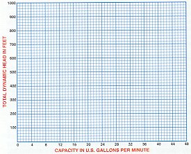
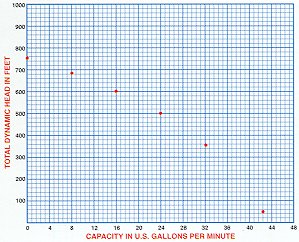
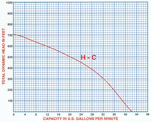
Let's think of a well all of water. We want to use the water in our home. The home is at a higher level than the water in the well. Since gravity won't allow water to flow uphill, we used a pump. A pump is a machine used to move a volume of water a given distance. This volume is measured over a period of time expressed in gallons per minute (GPM) or gallons per hour (GPH). The pump develops energy called discharge pressure or total dynamic head. This discharge pressure is expressed in units of measure called pounds per square inch (psi) or feet of head (ft). NOTE: 1 P.S. I will push a column of water up a pipe a distance of 2.31'. When measuring a pumps performances, we can use a curved to determine which pump is best to meet our requirements.
With the pump running a reading was taken from the gauge in PSI and converted to feet ( 1 psi - 2.31 feet ). We show another unit of measure in gallons
per minute across the bottom. You start with 0 on the left.
The numbers printed as you go to the right relate to the ability of the
pump to produce flow of water expressed as capacity -- in gallons per minute
[GPM]. Again, always determined the value of each grid line.
.
. 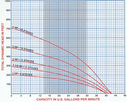 there are many different type curves shown in our catalog. Here is a composite performance curve (more than one pump) for the submergible. There is a separate curve for each horsepower size. Let's compare 2 sizes: 1. First look at the 1 HP, 8 stages (impellers
and diffusers). At 20 GPM capacity this model will make 160 feet.
When you add impellers, the pump makes more pressure (expressed in feet). This allows the pump to go deeper in the well, but also takes a more horsepower. |
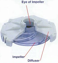 The
two main parts of the pump are the impeller and diffuser. The impeller
can be made of bronze, stainless steel, cast-iron, polycarbonate, and a
variety of other materials. A diffuser or volute houses the impeller
and captures the water of the impeller.
The
two main parts of the pump are the impeller and diffuser. The impeller
can be made of bronze, stainless steel, cast-iron, polycarbonate, and a
variety of other materials. A diffuser or volute houses the impeller
and captures the water of the impeller.
 The
jet pump is a centrifugal pump with one or more impeller and diffuser with
the addition of a jet injector. A JET INJECTOR consists of
a matching nozzle and venturi. The nozzle receives water at high-pressure.
As the water passes through the jet, water speed (velocity) is greatly
increased, but the pressure drops. This action is the same as the
squirting action you get with a garden hose as when you start to close
the nozzle. The greatly increased waters speed plus the lower pressure
around the nozzle tip, is what causes suction to develop around the jet
nozzle. Water around a jet nozzle is drawn into the water stream
and carried along with it.
The
jet pump is a centrifugal pump with one or more impeller and diffuser with
the addition of a jet injector. A JET INJECTOR consists of
a matching nozzle and venturi. The nozzle receives water at high-pressure.
As the water passes through the jet, water speed (velocity) is greatly
increased, but the pressure drops. This action is the same as the
squirting action you get with a garden hose as when you start to close
the nozzle. The greatly increased waters speed plus the lower pressure
around the nozzle tip, is what causes suction to develop around the jet
nozzle. Water around a jet nozzle is drawn into the water stream
and carried along with it.
 Water
is supplied to the Jet ejector under pressure. Water surrounding
the jet stream is lifted and carried up the pipe as a result of the jet
action.
Water
is supplied to the Jet ejector under pressure. Water surrounding
the jet stream is lifted and carried up the pipe as a result of the jet
action.
 A
convertible jet pump allows for shallow-well operation with the ejector
mounted on the end of the pump body. This time of pump can be converted
to a deep-well jet pump by installing the injector below the water level.
This is of particular value when you have a water level that is gradually
lowering. This will probably require a change of venturi to work
efficiently.
A
convertible jet pump allows for shallow-well operation with the ejector
mounted on the end of the pump body. This time of pump can be converted
to a deep-well jet pump by installing the injector below the water level.
This is of particular value when you have a water level that is gradually
lowering. This will probably require a change of venturi to work
efficiently.
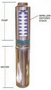 The
submergible pump is a centrifugal pump. Because all stages of the
pump end (wet end) and the motor are joined and submerged in the water,
it has a greater advantage of the over other centrifugal pumps. There
is no need to recirculate or generate drive water as with jet pumps, therefore,
most of its energy goes toward "pushing" the water rather than fighting
gravity and atmospheric pressure to draw water.
The
submergible pump is a centrifugal pump. Because all stages of the
pump end (wet end) and the motor are joined and submerged in the water,
it has a greater advantage of the over other centrifugal pumps. There
is no need to recirculate or generate drive water as with jet pumps, therefore,
most of its energy goes toward "pushing" the water rather than fighting
gravity and atmospheric pressure to draw water.