Cast Iron Soil Pipe & Fittings Handbook
Chapter 2 - Installation of Cast Iron Soil Pipe and Fittings
General Installation Instructions
-
Vertical Piping:
-
Secure vertical piping at sufficiently close intervals to keep the pipe
in alignment and to support the weight of the pipe and its contents. Support
stacks at their bases and at sufficient floor intervals to meet the requirements
of local codes. Approved metal clamps or hangers should be used for this
purpose.
-
If vertical piping is to stand free of any support or if no structural
element is available for support and stability during construction, secure
the piping in its proper position by means of adequate stakes or braces
fastened to the pipe.
-
Horizontal Piping, Suspended:
-
Support horizontal piping and fittings at sufficiently close intervals
to maintain alignment and prevent sagging or grade reversal. Support each
length of pipe by an approved hanger located not more than 18 inches from
the joint.
-
Support terminal ends of all horizontal runs or branches and each change
of direction or alignment with an approved hanger.
-
Closet bends installed above ground should be firmly secured.
-
Horizontal Piping, Underground:
-
To maintain proper alignment during backfilling, stabilize the pipe in
proper position by partial backfilling and cradling.
-
Piping laid on grade should be adequately secured to prevent misalignment
when the slab is poured.
-
Closet bends installed under slabs should be adequately secured.
-
Installation Inside the Building:
-
Installation suggestions. According to most authorities and plumbing codes,
it is sufficient to support horizontal pipe at each joint, i.e. 5' pipe
should be supported at five foot intervals, 10' in length may be supported
at ten foot intervals. Supports should be adequate to maintain alignment
and prevent sagging and should be placed within eighteen inches of the
joint.

When the system is filled with water, sufficient beam strength is provided
by cast iron soil pipe to carry the load with hangers every ten feet. Any
of the horizontal supports or clamps illustrated in Figures 1 and 2 may
be used, depending on conditions or what is regarded as essential by the
contractor, architect or engineer. Whatever method of support or clamp
is used for the horizontal line, care should be exercised to make certain
that the line has a proper grade (1/4 inch or more per foot).
Hangers may be fastened to wood members or beams with wood screws, lag
screws or large nails. For fastening to "I" beams, bar joists, junior beams
or other structural members, beam clamps or "C" clamps may be used. Fasteners
for masonry walls may be expansion bolts or screws, or where a void is
present, the toggle bolt may be used. Studs shot into the masonry by the
explosion method may also be used. Along a wall, a bracket made of structural
members or a cast bracket may be used.
Adequate provision should be made to prevent "shear". Where components
are suspended in excess of eighteen (18) inches by means of non-rigid hangers
they should be suitably braced against movement horizontally, often called
sway bracing. Examples of sway bracing are illustrated in Figures 3 and
4.

Figure 1 - Horizontal Pipe Supports

Figure 2 - Horizontal Pipe Supports (continued)

Figure 3 - Horizontal Pipe with Sway Brace

Figure 4 - Sway Brace
Horizontal Installation of Large Diameter Pipe.
Horizontal pipe and fittings five (5) inches and larger must be suitably
braced to prevent horizontal movement. This must be done at every branch
opening or change of direction by the use of braces, blocks, rodding or
other suitable method, to prevent movement or joint separation. Figure
5 illustrates several methods of bracing.
Suggested Installation of Horizontal Fittings.
-
Hangers should be provided as necessary to provide alignment and grade.
Hangers should be provided at each horizontal branch connection. Hangers
should be adequate to maintain alignment and prevent sagging and should
be placed adjacent to the coupling. By placing the hangers properly, the
proper grade will be maintained. Adequate provision should be made to prevent
shear. Where pipe and fittings are suspended in excess of eighteen inches
by means of non-rigid hangers they should be suitably braced against movement
horizontally, often called sway bracing. Refer to Figures 3 and 4 for illustrations.
-
Closet bends, traps, trap-arms and similar branches must be firmly secured
against movement in any direction. Closet bends installed above ground
should be stabilized. Where vertical closet studs are used they must be
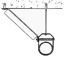
stabilized against horizontal or vertical movement. In Figures 6 and 7
see illustration for strapping a closet bend under a sub-floor and how
a clevis type hanger has been used to an advantage.
-
When a hubless blind plug is used for a required cleanout, the complete
coupling and plug must be accessible for removal and replacement.
-
The connection of closet rings, floor and shower drains and similar "slip-over"
fittings and the connection of hubless pipe and fittings to soil pipe hubs
may be accomplished by the use. of caulked lead and oakum or compression
joints.
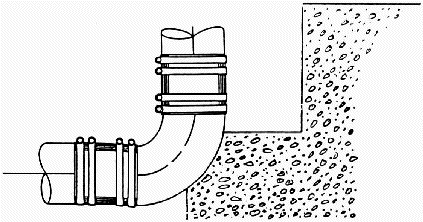
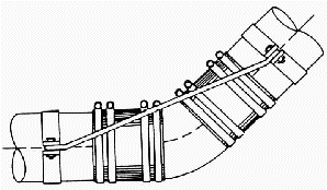 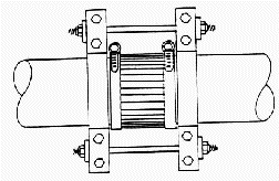
Figure 5 - Large Diameter Pipe
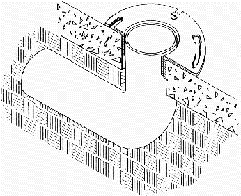
Figure 6 - Cross Section View of Closet Bend Showing Flange Properly
Secured
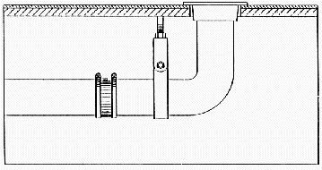
Figure 7 - Method of Using Hanger for Closet Bend
Seismic Restraints
The following recommendations are some of the factors to consider when
installing cast iron pipe in seismically active areas. All installations
must comply with local codes and instructions of architects or engineers
who are responsible for the piping design.
-
Brace all pipe 2" and larger.
Exceptions:
Seismic braces may be omitted when the top of the pipe is suspended
12" or less from the supporting structure member and the pipe is suspended
by an individual hanger.
-
Vertical Piping Attachment -
Vertical piping shall be secured at sufficiently close intervals
to keep the pipe in alignment and carry the weight of the pipe and contents.
Stacks shall be supported at their bases and if over two stories in height
at each floor by approved floor clamps. At vertical pipe risers, whenever
possible, support the weight of the riser at a point or points above the
center of gravity of the riser. Provide lateral guides at the top and bottom
of the riser, and at intermediate points not to exceed 30' 0" on center.
-
Horizontal Piping Supports -
Horizontal piping shall be supported at sufficiently close intervals
to prevent sagging. Trapeze hangers may be used. Pipe, where top of the
pipe is 12" or more from supporting structure shall be braced on each side
of a change of direction of 90 degrees or more.
-
Traverse bracing
40'- 0"o.c. maximum spacing unless otherwise noted. One pipe section
may act as longitudinal bracing for the pipe section connected perpendicular
to it, if the bracing is installed with 24" of the elbow or tee of similar
size.
-
Longitudinal bracing
80'- 0"o.c. maximum spacing unless otherwise noted.
-
Miscellaneous
a) Provide large enough pipe sleeves through walls or floors to allow
for anticipated differential movements.
WHERE MULTIPLE SHIELD AND CLAMP JOINTS OCCUR IN A CLOSELY SPACED
ASSEMBLY (I.E. FITTING-FITTING-FITTING, ETC.) A 16 GAUGE HALF SLEEVE MAY
BE INSTALLED UNDER THE ASSEMBLY WITH A PIPE HANGER AT EACH END OF THE SLEEVE.1
Method of supporting "multi-fitting" installations
(Hanger spacing 10 ft. max)
FIG. 8 - FOR SEISMIC BRACING ONLY
NOTE: Seismic braces may be installed at either hanger, braces at
both hangers are not required.
1Reprinted with permission of the Plumbing & Piping Industry
Council, Inc.
Vertical Piping.

Vertical components should be secured at each stack base and at sufficiently
close intervals to keep the system in alignment and to adequately support
the weight of the pipe and its contents. Floor clamps, sometimes called
friction clamps, are required for vertical piping in multistory structures
in order for each floor to carry its share of the load. Figures 11 and
12 show some typical brackets or braces for vertical piping. Figure 13
shows a method of clamping the pipe at each floor, using a friction or
floor clamp.
If vertical piping is to stand free of any support or if no structural
element is available for support and stability during construction, secure
the piping in its proper position by means of adequate metal stakes or
braces fastened to the pipe. 


|


